
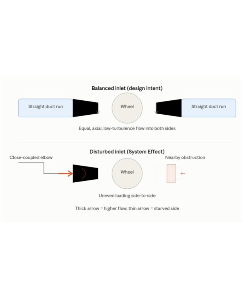
A DWDI fan can be correctly selected on paper and still underperform after installation.
In a double-width, double-inlet (DWDI) centrifugal fan, air enters the wheel from both sides. If the flow reaching the two inlets is uneven, turbulent, or swirling, the fan does not operate under the same conditions as it did during performance testing.
The result can be lower airflow, additional pressure loss, higher power consumption, noise, vibration, and unnecessary stress on the fan.
For this reason, inlet conditions should be considered part of DWDI fan selection and system design.
What Is a DWDI Fan?
A DWDI fan has a centrifugal wheel with two inlet openings, allowing air to enter from both sides of the wheel.
This configuration is used where high air volumes are required and is commonly found in large air-handling and industrial ventilation applications.
The important consideration is that both sides of the wheel need to receive suitable airflow. The fan performance shown on a manufacturer’s fan curve is based on defined test conditions. Actual field installation conditions can introduce additional losses that are not reflected in an idealized selection.
AMCA identifies these differences between laboratory and field conditions as system effect. System effect can occur at either the fan inlet or outlet when the airflow is disturbed by ductwork, fittings, dampers or other components.
Why DWDI Fan Inlet Conditions Matter
The inlet of a centrifugal fan should receive airflow that is as uniform and stable as the installation allows.
A poorly arranged inlet can produce:
- Uneven velocity across the fan inlet
- Turbulence
- Swirl or pre-rotation
- Unequal airflow entering the two sides of the wheel
- Additional pressure losses
- Uneven loading of the fan wheel
These conditions change the way air enters the impeller. The fan may then deliver less airflow than expected at the selected speed and pressure.
AMCA’s current site-performance standard specifically addresses flow distortion, including requirements concerning the velocity conditions at inlet boxes. In the standard’s test procedure, the mean gas velocity at the entrance of each inlet box is not permitted to differ by more than 5% in the specified assessment.
That illustrates an important engineering principle- airflow distribution at a DWDI fan inlet needs to be considered, not simply the total airflow entering the system.
Common Causes of Poor DWDI Fan Inlet Airflow
1. Elbows Installed Too Close to the Fan
A 90-degree elbow immediately upstream of a fan can create an uneven velocity profile.
Instead of approaching the fan uniformly, the air can enter one part of the inlet at a different velocity from another. The problem becomes more significant when the elbow is installed without adequate straight duct length or flow-control measures.
AMCA’s system-effect guidance identifies elbows close to a fan inlet as a common source of non-uniform airflow.
Where space permits, the duct arrangement should provide the fan with a more stable approach flow. Turning vanes may also be appropriate for certain elbow configurations.
2. Abrupt Duct Transitions
A sudden change in duct size or direction can disturb the velocity profile before the air reaches the fan.
For example, a poorly proportioned transition connected directly to an inlet can create areas of high velocity alongside regions where the air slows down or recirculates.
The transition should be designed to provide a controlled change in duct area and direction rather than forcing the airflow to make a sudden change immediately before entering the fan.
3. Poorly Designed Inlet Boxes
Inlet boxes are often used where the duct arrangement does not allow a direct connection to the fan.
However, simply adding an inlet box does not guarantee good airflow.
An inlet box with an unsuitable geometry can create dead zones, separation and uneven velocity distribution. AMCA has specifically highlighted poor aspect-ratio inlet boxes as a source of fan system effect.
For a DWDI fan, the design of the inlet boxes becomes particularly important because the two sides of the fan should receive appropriately distributed airflow.
4. Dampers and Other Obstructions
Dampers, filters, transitions and other components located close to the fan can influence the airflow entering the wheel.
A damper that is not properly positioned or is partially closed can introduce turbulence or swirl. An inlet damper can also create pre-rotation, changing the fan’s operating condition.
AMCA notes that even a fully open inlet vane damper can introduce losses, while closing the vanes changes the airflow and pressure characteristics of the fan.
The losses associated with accessories should therefore be included when evaluating the complete fan system.
Balanced Airflow Between the Two DWDI Inlets
For a DWDI fan, one of the most important considerations is the distribution of air between the two inlets.
The objective is not simply to achieve the required total CFM or m³/h.
Consider a system requiring 100,000 m³/h.
A design that provides approximately 50,000 m³/h to each inlet is fundamentally different from an arrangement where one side receives substantially more airflow than the other.
An imbalance can affect the loading of the wheel and the aerodynamic performance of the fan.
During design and commissioning, engineers should therefore consider:
- Airflow entering each inlet
- Velocity distribution
- Duct geometry
- Inlet-box geometry
- Location of elbows and dampers
- Possible recirculation
- Fan operating point
For critical industrial systems, airflow measurements can help confirm whether the installed system is behaving as expected.
Avoiding Swirl at the Fan Inlet
Swirling airflow is another important concern.
The fan wheel is designed to impart energy to the air in a particular direction. If the incoming air already has significant rotational motion, the fan is no longer operating with the same inlet condition assumed during its performance evaluation.
AMCA describes forced inlet vortices and inlet swirl as sources of system effect. The direction and strength of the swirl can influence fan performance and power requirements.
This is why an elbow, transition or other fitting should not be treated as just a connection between the duct and fan. Its aerodynamic effect matters.
What Should Be Checked in DWDI Fan Inlet Design?
Before finalizing the fan and duct arrangement, the following points should be reviewed:
Airflow requirement
Confirm the required operating airflow in m³/h or CFM.
Pressure requirement
Determine the actual system resistance rather than selecting the fan from airflow alone.
Air density
Temperature and altitude can change air density and therefore influence fan performance and power requirements. Current AMCA fan-selection guidance emphasizes correcting for air-density variations when evaluating fan performance.
Inlet arrangement
Review the duct approach to both fan inlets. Avoid arrangements that force sharp changes in direction immediately before the wheel.
Inlet-box geometry
Where inlet boxes are required, evaluate their geometry and the resulting velocity distribution rather than treating the box as a simple fabricated connection.
Accessories
Include the pressure losses and aerodynamic effects of dampers, filters, silencers and other components in the system calculation.
Operating point
Check where the selected duty point falls on the fan curve. A fan should be selected for stable and efficient operation rather than simply matching a nominal airflow value.
How Inlet Conditions Affect Fan Performance
The impact of poor inlet conditions can extend beyond a reduction in airflow.
A disturbed inlet can contribute to:
- Lower airflow: The fan may not deliver the expected volume at the installed operating speed.
- Higher system resistance: Turbulence and flow separation introduce additional losses.
- Higher energy consumption: Compensating for lost performance by increasing fan speed can increase power consumption.
- Maintenance problems: Persistent vibration and abnormal loading can affect bearings, shafts, belts and other components.
AMCA notes that system effects can increase energy consumption, noise and vibration and may contribute to premature component failure.
What About the Fan Outlet?
The air leaving a centrifugal fan does not immediately have a perfectly uniform velocity profile. Poorly positioned elbows or transitions close to the discharge can create additional system losses.
AMCA recommends providing sufficient effective duct length for the airflow to develop before major changes in direction. The appropriate arrangement depends on duct geometry and velocity, so fixed rules should not replace an engineering assessment.
The fan, inlet ductwork and outlet ductwork should therefore be evaluated as one system.
DWDI Fan Selection Should Include the Installation
A fan curve is only one part of the selection process.
The actual installation should be considered when determining whether a DWDI fan will achieve the required duty. This includes the duct layout, inlet conditions, outlet arrangement, accessories, air density and system resistance.
AMCA’s current fan-selection guidance emphasizes evaluating system effects and the actual operating conditions rather than relying on simplified rules of thumb.
For this reason, the best time to identify an inlet-flow problem is during system design, not after commissioning.
Final Takeaway
Atmax Filtration approaches DWDI fan selection as part of the complete air-moving system.
We can evaluate the required airflow and pressure, fan configuration, operating conditions and the connection between the fan and ductwork. Particular attention can be given to inlet and outlet arrangements where space constraints, elbows, transitions or other equipment may affect airflow distribution.
For industrial ventilation and air-handling applications, this approach helps ensure that the selected fan is suited not only to the specified duty point but also to the conditions under which it will operate.
A DWDI fan depends on more than its wheel size, RPM and rated airflow.
The conditions immediately upstream of the fan influence how effectively the wheel can operate. Uneven airflow, inlet swirl, poorly proportioned transitions, close-coupled elbows and unsuitable inlet boxes can introduce system effect and reduce the performance expected from the fan.
For a reliable DWDI installation, fan selection and airflow distribution should be designed together.