
How to select a Fan by Duty Point?
Picking a fan off the catalogue because the brochure shows a big airflow number is a classic, and costly, mistake. A fan doesn’t have one airflow. It has a whole range of airflow and pressure pairings, and which one you get depends on the system it’s plugged into. That’s why experienced engineers select fans by duty point.
Below, we’ll go through what a duty point actually is, how airflow and static pressure define it, how to read a fan curve, and how to use the familiar 10–25% margin rule without oversizing your fan.
What Is a Fan Duty Point?
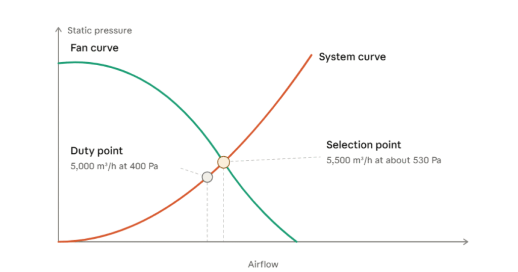
A duty point is simply the pairing of airflow (Q) and static pressure (Pₛ) the fan has to hit in your particular application. For example, a duty point might be 5,000 m³/h at 400 Pa.
Think of it as the target. Every fan comes with a performance curve, and a good selection is one where the fan’s curve passes through, or just above, this point while the fan runs efficiently and stably.
Duty point vs. operating point. The duty point is what you need. The operating point is where the fan actually runs, which is the intersection of the fan curve and the real system curve once installed. A good selection brings the two as close together as possible.
Step 1: Determine the Required Airflow
Airflow is how much air moves in a given time, usually written in m³/h, m³/s, L/s or CFM. How you work it out depends on the job:
- General ventilation: based on air changes per hour (ACH) or per-person fresh air rates. Airflow = room volume × ACH.
- Heat removal: Q = heat load ÷ (air density × specific heat × allowable temperature rise).
- Fume, dust or process extraction: based on capture velocity and hood or duct area.
- Cooling or HVAC coils: driven by the coil or air handling unit design flow.
Base this number on a clear design requirement, not a rule of thumb you can’t defend later. Any mistake here follows you through every step after it.
Step 2: Calculate the Total System Static Pressure
Static pressure is the resistance your fan has to push against to move air through the system. Add up every loss along the air path and you get the total, including:
- Straight duct friction losses
- Bends, elbows, transitions, dampers and fittings
- Filters (always use mid-life or dirty filter values, not clean ones)
- Heat exchangers, coils, silencers and attenuators
- Grilles, louvres, weather hoods and bird screens
- Entry and exit losses
Pressure loss rises roughly with the square of airflow. Double the airflow and resistance climbs roughly fourfold. That’s the shape of the system curve, and it explains why a modest bump in airflow can need a much bigger jump in pressure.
Static pressure or total pressure? Check that the catalogue data and your calculation are on the same basis. Mixing static and total pressure can throw you off by tens of pascals, particularly on axial and high-velocity systems.
Step 3: Understand the Fan Curve and System Curve
A fan curve plots pressure against airflow. At free delivery (no resistance) you get the most air and no pressure. At shut-off (fully blocked) it’s the reverse: maximum pressure, no air. Real operation always lands somewhere in between.
The system curve shows how much pressure your ductwork and components demand at each airflow. Where the two curves cross is the operating point.
When you study a fan curve, keep an eye on:
- Where your duty point sits. It should be comfortably to the right of the pressure peak, in the stable region of the curve.
- Efficiency. Aim for the duty point to fall near the fan’s best efficiency point (BEP), typically in the upper-middle of the efficiency island.
- Power curve. Check motor loading, especially on fans with a non-overloading characteristic versus those that can overload at high airflow.
- Sound levels. Noise rises sharply when a fan is pushed far from its best efficiency area.
Step 4: Apply the 10–25% Margin Rule
No calculation is perfect. Duct routes get changed on site, filters clog, dampers get closed down, and installations are rarely ideal. So designers add a safety margin to the duty point. A common working range is 10% to 25%, applied to airflow, pressure or both.
Situation | Typical margin |
Well-defined, simple system with accurate calculations | About 10% |
Typical commercial or industrial ventilation | 10–15% |
Uncertain duct layouts, future expansion, filter loading, retrofit work | 15–25% |
Critical processes where airflow loss is unacceptable | Upper end of the range, with justification |
A Worked Example
Say your calculated duty point is 5,000 m³/h at 400 Pa.
- Add a 10% airflow margin: 5,000 × 1.10 = 5,500 m³/h.
- Because pressure follows the square of airflow along the system curve, the pressure at the higher flow becomes 400 × (1.10)² ≈ 484 Pa.
- If you also want allowance for filter loading and unknown losses, a further 10% on pressure brings the selection point to roughly 530 Pa.
So you’d select a fan that delivers about 5,500 m³/h at 530 Pa. Note that a 10% margin on airflow isn’t a 10% margin on pressure. Overlooking that is how many systems end up falling short.
For a rough idea of the power involved: air power = airflow (m³/s) × pressure (Pa). At 5,500 m³/h (1.53 m³/s) and 484 Pa, that is about 740 W. Divide by an overall efficiency of around 70% and you get roughly 1.05 kW at the shaft, a useful starting point for sizing the motor with proper headroom.
5. The Risk of Over-Margining
More margin isn’t automatically safer. Stack one on the airflow, another on the pressure and a third by rounding up to the next size, and you quickly end up with a fan that’s far too big. The usual fallout:
- Poor efficiency. The fan runs away from its best efficiency point and wastes energy.
- Higher noise and vibration. Throttling an oversized fan with dampers raises noise levels.
- Unstable operation. Running too far left on the curve can cause stall, surging and pulsation.
- Higher capital and running costs. A larger fan, motor, starter and cabling all cost more.
- Reduced fan and motor life.A better habit is to apply one clearly documented margin, explain why it’s there, and let speed control handle the fine-tuning on site.
6. Use Fan Laws and Speed Control to Your Advantage
The fan affinity laws tell you how a fan responds when its speed changes:
- Airflow is proportional to speed.
- Pressure is proportional to speed squared.
- Power is proportional to speed cubed.
That’s why pairing a slightly generous selection with a variable frequency drive (VFD) or an EC motor works so well. You can commission the fan right at the real duty point, then turn the speed down as conditions allow and save a lot of energy. Cut the speed by 20% and power drops by roughly half.
7. Correct for Air Density, Altitude and Temperature
Catalogue ratings are normally based on standard air density (about 1.2 kg/m³ at 20°C at sea level). If your application involves high temperatures, high altitude or humid, dusty air, the density changes, and so does the pressure the fan develops.
Thinner air means the fan produces less pressure and draws less power at the same speed. Either convert your duty point back to standard conditions or use manufacturer software that accounts for actual density.
Choosing the Right Fan Type for the Duty Point
Once airflow and pressure are pinned down, the duty point usually narrows the choice of fan type:
- Axial fans: high airflow, low to medium pressure. Ideal for wall-mounted ventilation, cooling towers and short ducts.
- Centrifugal fans (backward curved): medium to high pressure, good efficiency, suitable for filtered systems and air handling units.
- Centrifugal fans (forward curved): compact, lower pressure, widely used in residential and light commercial HVAC.
- Mixed flow and inline fans: a balance of pressure and flow in a compact in-duct format.
- Plug fans (EC): efficient and space-saving for air handling units.
Fan Selection Checklist
- Define the required airflow with a documented basis.
- Calculate total system static pressure, including dirty-filter conditions.
- Confirm whether you are working in static or total pressure.
- Apply one justified margin in the 10–25% range.
- Correct for air density, altitude and temperature.
- Add a system effect allowance where installation is less than ideal.
- Plot the duty point on the fan curve and confirm it sits in the stable, efficient region.
- Check motor power, noise and available speed control.
- Verify the selection against the manufacturer’s certified performance data.
Conclusion
Selecting a fan by duty point comes down to matching it to what the system really needs, not to the biggest figure in a brochure. Pin down your airflow, add up the static pressure honestly, apply one sensible margin of 10–25%, and check the result against the fan curve. Add speed control for fine-tuning and you’ll have a system that’s quiet, efficient and reliable.
Not sure which fan fits your application? Take your airflow, static pressure and operating conditions to a qualified fan specialist and ask them to confirm the selection against certified performance data. You can also reach out to us at sales@atmaxfiltration.com
Frequently Asked Questions
Static pressure is the resistance the fan must overcome in the system, while total pressure adds velocity pressure on top. Whichever you use, compare like with like when reading catalogue data
Most designers add somewhere between 10% and 25%, depending on how confident they are in the numbers. Simple, well-defined systems stay near 10%; uncertain or expandable ones go higher.
Not really. An oversized fan wastes energy, makes more noise and can end up in an unstable part of its curve. A sensibly margined fan with speed control does the job better.
The fan can slip into the stall region, which means unstable airflow, vibration, noise and a shorter working life. Choose a fan whose curve puts your duty point to the right of the peak.
That depends on where the uncertainty is. Put it on airflow if demand might grow, and on pressure if the system losses are shaky. Just remember pressure moves with the square of airflow.