
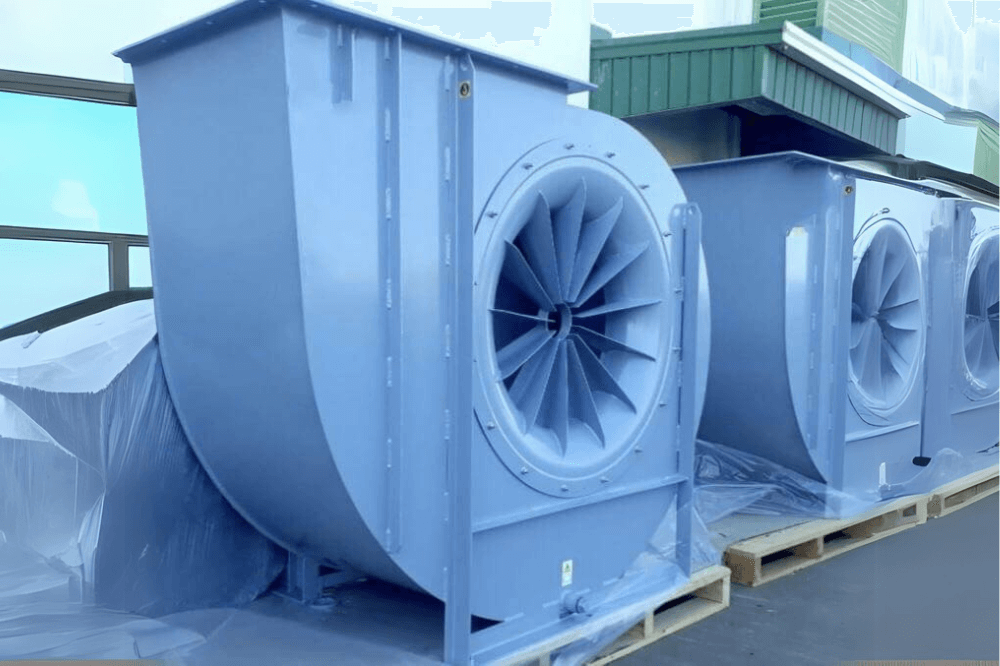
Walk into any manufacturing plant and you’ll find centrifugal fans move hot air from furnaces, capture welding fumes, extract dust from production lines, and keep critical processes running safely.
A centrifugal fan that is too small won’t deliver the airflow your process needs. One that’s oversized can increase energy costs, create unnecessary noise, and shorten the life of bearings, belts, and motors. In many cases, the problem isn’t the equipment itself. If selecting a fan without fully understanding the system it’s working in.
Proper fan sizing goes beyond choosing a fan with a certain airflow rating. You need to understand how much air the process requires, the resistance created by the ductwork, filters, dampers, and other components, as well as the operating conditions inside the facility.
In this guide, we’ll walk through the key factors engineers use to size a centrifugal fan correctly, helping you improve system performance, reduce operating costs, and extend equipment life.
Why Proper Centrifugal Fan Sizing Matters
Choosing the right centrifugal fan affects far more than airflow. It influences the efficiency, reliability, and operating cost of your entire ventilation system.
When a fan is properly matched to the application, you can expect:
- Consistent airflow throughout the process
- Lower energy consumption
- Better dust and fume extraction efficiency
- Stable operating temperatures
- Reduced maintenance requirements
- Longer bearing and motor life
- Lower operating noise
- Improved overall system reliability
On the other hand, an incorrectly sized fan often leads to poor air distribution, excessive power consumption, higher maintenance costs, and frequent operational adjustments.
Step 1: Calculate the Airflow Requirement (CFM)
Every fan selection starts with one basic question:
How much air does your facility actually need to move?
This value is typically measured in CFM (Cubic Feet per Minute) or m³/hr, depending on the region and industry.
The required airflow varies significantly depending on the application.
For example:
Dust Collection Systems
The airflow depends on several factors, including:
- Number of dust collection points
- Hood or pickup design
- Dust generation rate
- Required conveying velocity
- Type of material being collected
Consider a facility with the following equipment:
Equipment | Required Airflow |
Grinding Station | 1,200 CFM |
Welding Booth | 2,500 CFM |
Bag Dump Station | 1,800 CFM |
The total airflow requirement becomes:
1,200 + 2,500 + 1,800 = 5,500 CFM
However, airflow alone doesn’t determine the fan size. The fan must also overcome the resistance created by the entire ventilation system.
That’s where static pressure comes into the picture.
Step 1: Determine the Required Airflow (CFM)
The first step is calculating the required airflow.
Airflow is typically measured in:
- CFM (Cubic Feet per Minute)
- m³/hr
- m³/s
The required airflow depends on the application.
Dust Collection
Airflow depends on:
- Number of pickup points
- Hood design
- Dust generation rate
- Transport velocity
Example:
Equipment | Required Airflow |
Grinding Machine | 1,200 CFM |
Welding Booth | 2,500 CFM |
Bag Dump Station | 1,800 CFM |
Total airflow:
1,200 + 2,500 + 1,800 = 5,500 CFM
Process Ventilation
For heat removal:
Airflow depends on:
- Heat load
- Desired room temperature
- Air changes per hour
- Equipment operating conditions
For general ventilation:
Engineers typically calculate airflow using Air Changes per Hour (ACH).
Step 2: Calculate Static Pressure
After determining airflow, calculate the total static pressure (TSP).
Static pressure represents the total resistance that the fan must overcome.
It includes:
- Straight duct losses
- Elbows
- Dampers
- Filters
- Cyclones
- Dust collectors
- Heat exchangers
- Silencers
- Hoods
- Stack losses
The equation is:
Total Static Pressure = Sum of all pressure losses
Example:
Component | Pressure Loss |
Inlet Hood | 0.6 in. WG |
Ductwork | 2.1 in. WG |
Filters | 2.4 in. WG |
Cyclone | 2.8 in. WG |
Elbows | 0.9 in. WG |
Total:
8.8 inches WG
This becomes the design static pressure.
Step 3: Consider Air Density
Fan performance changes with air density.
Density depends on:
- Temperature
- Altitude
- Humidity
- Gas composition
For example: Hot air is less dense than cold air.
A fan moving 5,000 CFM at 70°F behaves differently than the same fan moving air at 500°F.
Ignoring density corrections can result in significant performance errors.
Step 4: Identify the System Resistance Curve
Every ventilation system has a resistance curve.
As airflow increases:
- Pressure loss increases.
- Fan power demand rises.
The resistance curve intersects the fan performance curve at the operating point.
That operating point determines:
- Actual airflow
- Actual static pressure
- Brake horsepower
- Fan efficiency
Step 5: Read the Fan Performance Curve
Every centrifugal fan manufacturer provides performance curves showing the relationship between airflow, static pressure, efficiency, power, and speed.
A typical fan curve includes:
- Airflow (CFM)
- Static pressure
- Fan speed (RPM)
- Brake horsepower (BHP)
- Efficiency (%)
The ideal operating point is typically near the Best Efficiency Point (BEP), where the fan delivers maximum airflow with minimum energy consumption and reduced vibration.
Step 6: Select the Appropriate Fan Type
Different centrifugal fan designs are optimized for different applications.
Backward Curved Fans
Best for:
- Clean air systems
- HVAC
- General ventilation
- High efficiency applications
Advantages:
- Highest efficiency
- Lower power consumption
- Stable operation
Radial Blade Fans
Suitable for:
- Dust collection
- Abrasive particles
- High temperatures
- Material handling
Advantages:
- Rugged construction
- Handles dirty air
- Easy maintenance
Forward Curved Fans
Used for:
- HVAC systems
- Low-pressure applications
- Compact installations
Advantages:
- High airflow
- Lower operating pressure
- Quiet operation
Airfoil Fans
Preferred for:
- Clean industrial processes
- Energy-efficient systems
- Large ventilation systems
Advantages:
- Very high efficiency
- Low operating cost
Step 7: Calculate Motor Power
Motor size depends on:
- Airflow
- Static pressure
- Fan efficiency
- Safety factor
A commonly used equation is:
BHP = (CFM × Static Pressure) ÷ (6,356 × Fan Efficiency)
For motor selection, include a service factor to accommodate startup conditions and future operating variations. Choosing a motor with some reserve capacity helps prevent overload under peak demand.
Step 8: Check Noise Requirements
Industrial fans can produce significant noise.
Consider:
- Fan speed
- Blade design
- Tip velocity
- Silencers
- Acoustic insulation
Lower RPM fans generally produce less noise and have longer bearing life.
Step 9: Plan for Future Capacity
Industrial facilities often expand production over time.
Allowing 10–20% additional airflow capacity can reduce the need for major upgrades later, provided the fan still operates near its best efficiency range.
Common Fan Sizing Mistakes
Avoid these common errors:
- Selecting a fan based only on CFM
- Ignoring static pressure losses
- Oversizing the motor unnecessarily
- Neglecting air density corrections
- Using incorrect duct velocity assumptions
- Ignoring filter pressure drop over time
- Operating far from the Best Efficiency Point (BEP)
- Choosing the wrong impeller design for the application
Example: Fan Sizing Calculation
A manufacturing plant requires:
- Airflow: 12,000 CFM
- Static Pressure: 7.5 in. WG
- Air Temperature: 120°F
Engineering process:
- Calculate airflow requirement.
- Determine system resistance.
- Apply air density correction.
- Select a fan curve that delivers 12,000 CFM at 7.5 in. WG.
- Verify operation near the Best Efficiency Point.
- Select the appropriate motor with an adequate service factor.
- Confirm acceptable noise levels and space requirements.
Additional Factors That Influence Fan Selection
Besides airflow and pressure, engineers should evaluate:
- Corrosive or abrasive materials
- Continuous or intermittent duty
- Ambient and process temperatures
- Spark-resistant construction requirements
- Explosion-proof motors for hazardous locations
- Material of construction (carbon steel, stainless steel, FRP)
- Belt-driven versus direct-driven configurations
- Variable Frequency Drive (VFD) compatibility
Why Engineering Support Matters
Fan selection involves balancing airflow, pressure, efficiency, and lifecycle costs. A comprehensive evaluation, including duct layout, pressure losses, operating conditions, and future expansion, helps ensure dependable performance and minimizes energy consumption over the life of the system.
Working with experienced engineers can help optimize the entire ventilation system rather than simply selecting a fan from a catalog.
Conclusion
Sizing a centrifugal fan correctly requires more than matching airflow requirements. A reliable design considers airflow (CFM), total static pressure, air density, system resistance, fan performance curves, motor sizing, and application-specific operating conditions.
When these factors are evaluated together, the result is a ventilation system that operates efficiently, delivers consistent airflow, reduces energy costs, and provides long-term reliability.
For facilities handling dust collection, process ventilation, heat extraction, or industrial exhaust systems, investing time in proper fan sizing is one of the most effective ways to improve overall system performance and reduce total cost of ownership.